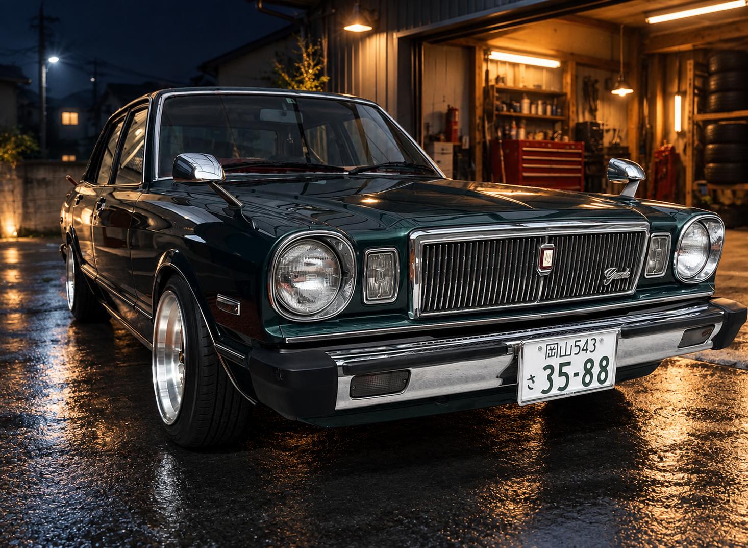
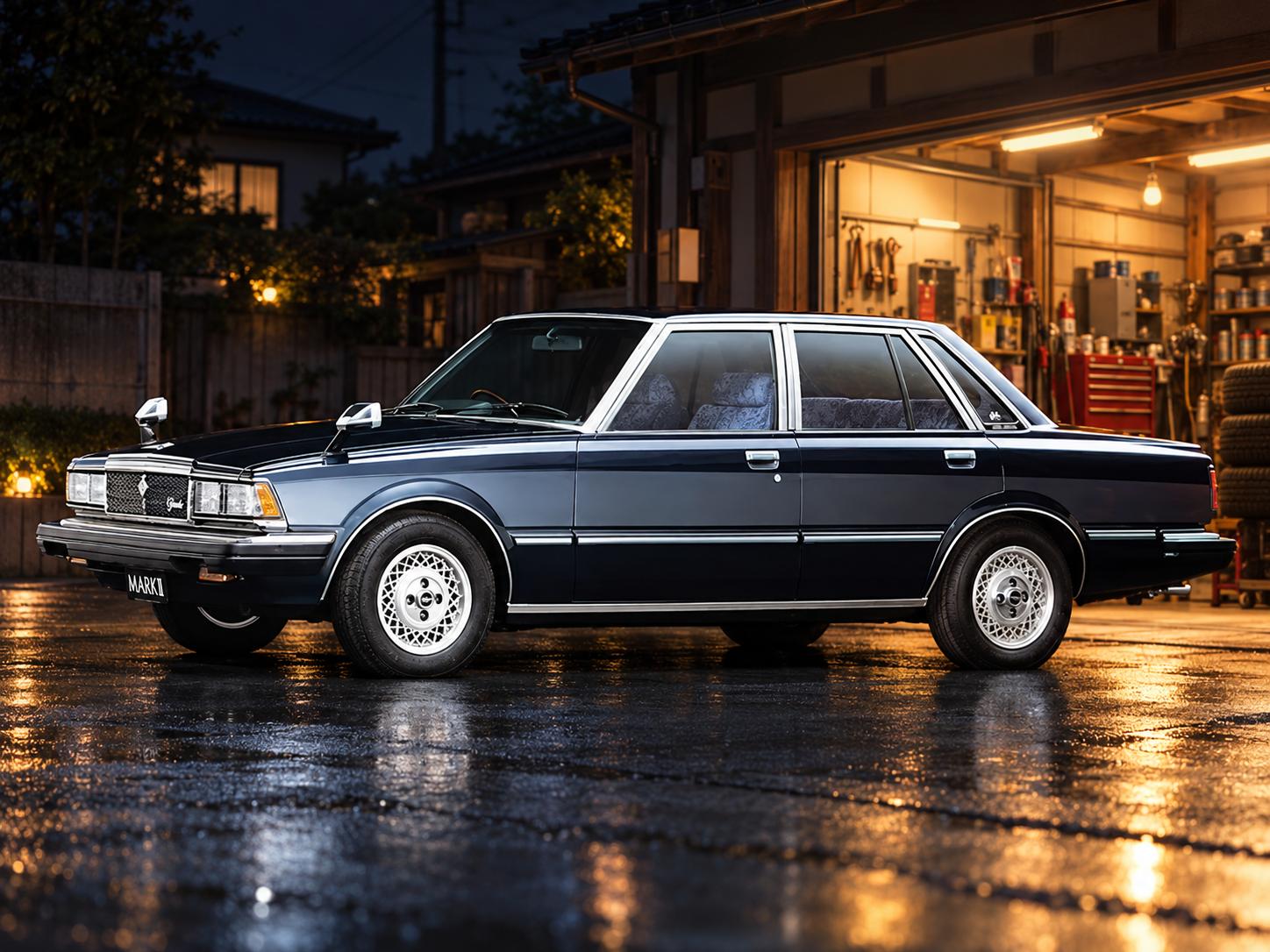
Автор — Pim25
Все нижеизложенное практически идентично на х60(х61) кузове.
Как известно, часть наших машин имеет сзади зависимую подвеску, а часть – независимую. (х40 мост, х41 независимая)
Плюсы и минусы есть и у того, и у другого типа. Но всегда существует какое-то количество автовладельцев, желающих поменять на своём авто один тип подвески на другой.
В данном разделе постараюсь быть полезным тем, кто задумал заменить «мост» на «привода» на автомобиле «Mark II» серии х30-40.
Это не отчёт – информация изложена скорее в виде рекомендаций для тех, кто твёрдо решил произвести описанные ниже процедуры, поэтому здесь нет фото самого процесса. Увлекательным это чтиво не назовёшь, да я к этому и не стремился.
Вполне возможно, что где-то в моём описании вы заметите неточности или несостыковки, а то и вовсе конструктивный промах – убедительно прошу не стесняться и сразу написать об этом в комментариях! Чем больше толковых замечаний – тем больше пользы следующим пользователям, я считаю.
Перед тем, как приступить к выполнению работ, внимательно прочтите описание процесса до конца – оцените свои навыки и ресурсы, а также наличие необходимого оборудования.
Изменения, которые вы вносите в конструкцию автомобиля, необратимы – их нельзя будет «откатить» назад в обратном порядке.
Обращаю ваше внимание, что большинство работ производится под кузовом автомобиля, который должен быть надёжно закреплён!
Всегда работайте вдвоём с помощником, который находится не под автомобилем и может помочь в случае необходимости!
В процессе выполнения работ вам придётся иметь дело с ядовитыми жидкостями, попадание которых внутрь организма или вдыхание паров которых может вызвать тяжёлое отравление и даже смерть!
При выполнении работ по резке, зачистке и сварке металла обеспечивайте противопожарную безопасность и держите под рукой огнетушитель и песок!
Всегда делайте паузы в процессе работы и хорошо проветривайте помещение!
Помните, что от качества вашей работы прямо зависит дальнейшая безопасная эксплуатация вашего автомобиля!
Не старайтесь завершать работы к какому-либо сроку – помните, что при реставрации мы получаем удовлетворение от процесса, и время в данном случае работает на нас.
Внимание! В процессе переделки будут затронуты следующие системы автомобиля:
— Кузов
— Рабочая тормозная система
— Стояночный тормоз
— Трансмиссия
— Подвеска
— Система выпуска
Начальные вводные: имеем машину «с мостом» (зависимой подвеской), на которую хотим поставить «привода» (независимую подвеску) от кузова-донора.
Далее для краткости я буду называть нашу машину с зависимой подвеской («мостом») сокращённо «40», а кузов донора с независимой («приводами») просто «41». Цифры условные, взяты для удобства.
Схема 1. Рычаги, линки и стабилизатор.
(1) – поперечный стабилизатор
(2) – кронштейн стабилизатора
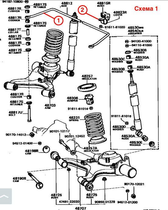 Схема 1
Схема 2. Большая и малая поперечные балки.
(1) – сложный болт с двойной резьбой
(2) – шайба с “поводком”
(3) – “нос” балки с креплением для редуктора
(4) – поперечный сайлент-блок
(5) – малая поперечная балка
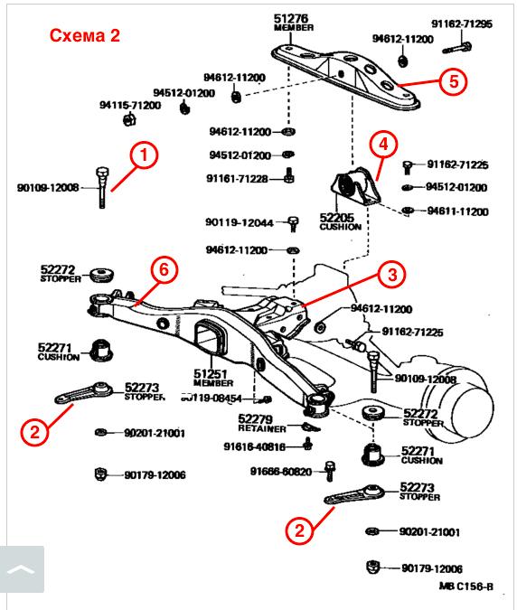 Схема 2
Фото 1. Особенности независимой подвески.
1 – Тройник тормозных магистралей
2 – Оконечные кронштейны тормозных магистралей кузова (2 шт.)
3 – Кронштейн троса стояночного тормоза (2 шт.)
4 – Место закладной болта основной поперечной балки (2 шт.)
5 – Резьбовая закладная для крепления шайбы с «поводком» (2 шт.)
6 – Накладки с резьбой для малой балки и стабилизатора (2 шт.)
7 – Кронштейн стабилизатора
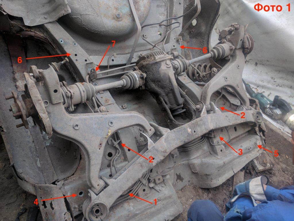 Фото 1
КУЗОВ
Если поочерёдно заглянуть в багажники стоящих рядом машин с мостом и независимой подвеской, то можно увидеть некоторую разницу в местах верхнего крепления амортизаторов относительно арки колеса.
Также разница наблюдается и в расположении верхних опорных площадок пружин (это видно уже при взгляде под арки задних крыльев).
Кроме того, различны углы, под которыми расположены резиновые отбойники (внутри пружин). Сами отбойники тоже отличаются (впрочем, как и пружины с амортизаторами).
Всё это обусловлено разницей в конструкции и иной артикуляцией колёс (рычагов) при ходах независимой подвески.
Таким образом, замена этих трёх мест на кузове (площадки пружины, опоры аморта и отбойника) – первый шаг при смене зависимой подвески на независимую.
Однако перед началом работ на нашей машине следует отключить аккумулятор и сделать следующее:
1) Снять выхлопную систему от катализатора (или приёмной трубы) до конца;
2) Открутить и снять карданные валы в сборе с промежуточной опорой;
3) Демонтировать тросы ручного тормоза;
4) Слить тормозную жидкость из системы и открутить задний тормозной шланг от моста;
5) Снять пружины с опорными резинками и амортизаторы;
6) Удалить мост в сборе с четырьмя продольными тягами и поперечной тягой Панара;
7) Отключить проводку и шланги от топливного бака, действуя снизу и сверху — через лючок в полу багажника справа (прикручен шурупами). О количестве и назначении шлангов написано вот по этой ссылке.
8) Снять топливный бак и его горловину. Перед снятием топливного бака сливаем топливо! Ослабляем хомуты резинового шланга, соединяющего бак с горловиной (под правым крылом). Горловину затем снимаем отдельно, действуя через заправочный лючок;
9) Демонтировать бензонасосную станцию, отсоединив её от трубок и шлангов;
10) Разобрать и унести салон позади передних сидений – полностью, включая карты задних дверей (либо полностью снять задние двери), а также ковёр на полу;
11) Удалить теплоизоляцию с арок задних крыльев и с пола задних пассажиров со стороны салона.
12) Очистить багажник от содержимого на 100%, включая ковры и обивку.
Вот теперь, наконец, мы можем приступить к замене упомянутых выше мест крепления. Положительный момент в том, что все эти три места (площадка пружины, опора аморта и отбойник) размещены на отдельном, приваренном снизу кузовном элементе (назовём его условно «полусферой»). На машине их два – по одному с каждого борта, их нужно очистить и аккуратно высверлить сверлом 9-10 мм (по паре элементов на машине и на доноре – всего 4), а затем отделить при помощи острого металлического инструмента (зубила, надёжного сапожного ножа, старой стамески и т.п.)
Работы сначала ведутся под правой и под левой арками крыла снизу, точно по точкам сварки – их там примерно два десятка с каждой стороны.
При этом на доноре «41» можно сверлить насквозь, а вот на машине «40» нужно стараться просверливать только один слой металла – на самих элементах-полусферах, а металл кузова не трогать.
Однако данные полусферы, даже будучи отсверленными, просто так не снимутся.
Для их снятия необходимо со стороны багажника сначала высверлить небольшие урезанные конусы, установленные вверху на арке каждого крыла – в этих усилителях закрепляются штоки амортизаторов. Эти конусы двойные и образованы внешним конусом, накладываемым со стороны багажника, и внутренним, вставляемым снизу и, по сути, являющимся частью нижней полусферы. Внутренний конус нужно отсверлить во вторую очередь (на кузове «40» опять сверлим только один слой металла – сам конус!).
Вот теперь мы сможем снять и получаем две полусферы с конусами от «40», которые откладываем в сторону, и две полусферы с конусами от «41», с которыми будем работать дальше.
Итак, на данном этапе мы держим в руках четыре (а строго говоря – шесть) элементов от «41», которые нужно приварить к «40».
Если они имеют следы коррозии на внутренних полостях – самое время их ликвидировать и нанести слой цинкового грунта. Он, в отличие от других ЛКМ, не будет препятствовать привариванию элементов к кузову. Не забудьте снять и отложить резиновые заглушки с больших полусфер – они нам пока не нужны.
(Где-то на этом этапе можно срезать с кузова проушины крепления продольных и поперечных тяг моста)
Зачистите турбинкой остатки сварных точек полусфер на кузове и металл вокруг них.
Подгоните и приварите 6 элементов к кузову.
(Знаю, что в этих четырёх-пяти словах может уместиться несколько дней работы – но будьте упорными и терпеливыми, и всё получится. Назад пути у вас уже нет ?).
Для приваривания используем углекислотный полу-автомат. Привариваемся к кузову только за круговые края отверстий на деталях, образованные при высверливании точек – получая таким образом весьма сходный с точечной сваркой конструктив.
Обратите внимание на последовательность приваривания: последним приваривается внешний конус со стороны багажника. Правильно ориентируйте детали! Конусы в багажнике должны быть плотно сомкнуты вершинами и приварены друг к другу.
Для облегчения работы с полусферами можно использовать вытяжные заклёпки, которые используем для закрепления детали в 3-4 точках после точной подгонки. После прихватывания детали сваркой заклёпки можно удалить (высверлить), а отверстия от них заварить.
Предвижу ваши вопросы – «А подойдут ли элементы от донора «41» к кузову «40»?»
К счастью, да! Мы просто повторяем путь производителя, который при сварке кузова на заводе ставил ту или иную полусферу в зависимости от типа кузова (подвески) авто. Это верно и для конусов, и для остальных рассматриваемых элементов.
После приваривания защищаем сварку от коррозии, покрывая герметиком и ЛКМ.
Итак, мы изменили конфигурацию верхней опоры для пружин и амортизаторов, однако сварочные работы по кузову на этом не заканчиваются!
РАБОЧАЯ ТОРМОЗНАЯ СИСТЕМА
Конфигурация задних тормозных магистралей «41» отличается от таковой на «40». Отличия в следующем.
К мосту «40» жидкость подводится всего одним шлангом, а далее по мосту стальной трубкой, закреплённой на балке, распределяется по колёсам.
В случае с независимой подвеской «41» всё немного сложнее. Трубка основной магистрали подходит к тройнику 1 (см. фото 1), закреплённому на днище. От тройника трубки опять же по днищу раздельно подходят к правому и левому борту и закрепляются в приваренных к кузову оконечных кронштейнах 2. От кронштейнов уже идут шланги, опускаясь на рычаги подвески. Далее по плоскости рычага опять идут короткие трубки, заканчивающиеся кронштейном, в котором осуществляется переход на шланги – а, они, в свою очередь, транспортируют жидкость непосредственно к суппортам. Все трубки и шланги варианта с независимой подвеской схематично изображены на схеме по ссылке.
Поэтому первым делом отсверливаем кронштейны 2 от донорского кузова (не страшно просверлить насквозь), тщательно замеряем их расположение на доноре, и переносим эту позицию на кузов «40». Зачищаем это место до металла, и привариваем кронштейны в нужном положении. Затем детали грунтуем, красим и т.п.
Далее где-то в районе окончания основной тормозной магистрали находим в днище точку с резьбой М6 и подходящим по длине болтом прикручиваем туда тройник 1, снятый с кузова «41». Если точка с резьбой не обнаруживается (или до неё не хватает основной трубки), то у вас два варианта действий: а) удлинить основную магистраль до тройника и потом использовать трубки с донора и б) поставить тройник в месте окончания основной магистрали, просверлив днище насквозь и установив гайку со стороны салона, а затем изготовить новые трубки, идущие до боковых кронштейнов справа и слева.
Как удлинять тормозные трубки и изготавливать новые, описано здесь.
Если на трубке тормозной магистрали на «40» был установлен так называемый «колдун» (регулятор тормозных усилий), связанный с мостом – его следует удалить.
Кроме того, следует обратить внимание на параметры ГТЦ (главного тормозного цилиндра), расположенного в моторном отсеке (на нём установлен бачок с запасом тормозной жидкости). Вполне возможно, что к задним барабанным тормозам при торможении отправляется иное количество тормозной жидкости, нежели к дисковым (зависит от строения и хода поршня),
Несогласованность в данном аспекте может поставить под вопрос эффективность торможения. Тогда встанет вопрос о замене ГТЦ или его поршневой части на аналогичные от «41».
СТОЯНОЧНЫЙ ТОРМОЗ
Тросы стояночного тормоза в оболочке для независимой подвески также отличаются – как по конструкции, так и по способу крепления.
Во-первых, «41» имеет дополнительные приваренные к кузову кронштейны, крепящие трос (внутри тоннеля для кардана).
Эти кронштейны необходимо отсверлить от донорского кузова и перенести на «40», предварительно отделив их от пластмассовых втулок троса (при этом сохранив втулки в целостности, что довольно нелегко).
Во-вторых, на «41» ближе к поперечной балке закреплены мощные площадки-кронштейны 3 (см. Фото 1), являющиеся упорами для оболочек тросов на пути к колёсам. Они крепятся болтами к днищу машины. На «40» отсутствуют закладные для их крепления, так что тут придётся «покумекать» (например, применить крепление гайкой из салона или нарезать резьбу в днище). Кроме того, на днище «40» не хватает опорных выступов лонжерона под эти площадки, которые позволили бы точно центрировать проход тросов сквозь балку (через центры сквозных проёмов-трубок) на пути к рычагам. Чтобы компенсировать отсутствие опоры, следует подложить под кронштейны прокладки из толстой фанеры или текстолита, подогнанные под форму днища и с отверстиями (лучше сделать это после установки балки).
Ситуация осложняется тем, что со стороны салона в этом районе проходит лонжерон замкнутого поперечного сечения (который, впрочем, мы далее будем вскрывать).
Донорский стояночный трос от «41» устанавливаем после монтажа балки подвески с рычагами, перед установкой карданных валов.
ПОДВЕСКА
Что касается крепления подвески, то здесь есть над чем поработать 🙂 и также не обойтись без приваривания элементов от донора.
Конструкция задней подвески на «41» предусматривает прежде всего крепление основной поперечной балки (6) к кузову автомобиля двумя мощными болтами (1) (см. Схему 2). Это уникальные болты, имеющие переменное сечение и две разные резьбы на теле – на первой трети и на последней трети. Резьбой большого диаметра (возле головки) через отверстие в лонжероне 4 (см. Фото 1) они вкручиваются в днище со стороны салона, а на резьбе меньшего диаметра (на последней трети болта) закрепляется снизу гайкой собственно балка. Так вот, в кузове «40» нет закладной под этот болт. Всё, что мы видим – это отверстие вытянутой формы, к которому никак не прикрепишь наш сложный болт.
Ок, идём к кузову «41» и смотрим, как дело обстоит там. Для получения полной картины нам нужно на доноре со стороны салона вскрыть поперечный лонжерон (выпилить на нём крышечку размерами примерно 12х12 см) над тем местом, где сложные болты были вкручены в кузов (ориентируемся по большому отверстию с резиновой заглушкой со стороны салона). Тогда мы увидим, что внутри лонжерона находится вваренная точечной сваркой закладная с гайкой под наш болт. И что мы делаем? Правильно – отсверливаем закладную (это тоже площадка примерно 10х10 см с загнутыми краями) вместе с приваренной к ней гайкой.
Но сначала точно замеряем положение сложного болта (вернее, его гайки) относительно контрольных точек на днище автомобиля.
Теперь аналогичное «вскрытие» поперечного лонжерона со стороны салона нам необходимо произвести на кузове «40» нашей машины. Рекомендую снять чуть меньшую площадку, чем на доноре – это может пригодиться (а можно вообще резануть только по трём сторонам и отогнуть).
В полученный отсек необходимо поместить закладную с гайкой от донора «41».
Дальше есть два варианта возможных действий: а) приварить закладную и б) посадить закладную на несколько крепёжных болтов, оставив возможность для её продольного перемещения в случае необходимости.
Первый вариант требует наличия уже собранной и прикреплённой к кузову всей остальной подвески, второй же оставляет свободу для маневра в будущем.
Всё дело в том, что точность расположения и прикрепления этих закладных на данном этапе определяет положение колеса ровно по центру арки (если смотреть сбоку) в дальнейшем. Можно пойти другим путём – довериться нашим измерениям относительно контрольных точек. Однако тут есть одно «но». Точно скопировать положение болта (гайки) не удастся ввиду того, что лонжерон, в который она закладывается, имеет на «41» слегка другую форму – в частности, там есть неглубокая выштамповка под сайлент-блоки балки – которой мы не наблюдаем на «40».
Поэтому в данном случае решение – за вами. В любом варианте крепить закладные следует, вкрутив в них сложные болты и надев балку снизу – так мы по крайней мере получаем истинное расстояние между болтами.
В дальнейшем (после полного окончания работ с подвеской) вырезанную нами «крышку» от лонжерона «41» можно приварить к нашей машине «40», сориентировав её так, чтобы отверстие в ней с резиновой заглушкой находилось точно над головкой сложного болта.
Теперь о монтаже самой балки. После надевания резино-шайб и балки на болты под гайку подкладываются пластины (2) (см. Схему 2) особой формы, и гайка затягивается. Эти пластины имеют «поводок» который должен быть закреплён на кузове болтом М8. Резьбовые закладные 5 (см. Фото 1) в кузове для этого имеются, но просто так закрепить поводок не получится. Как я уже упоминал, в лонжероне «40» нет выштамповки под балку, да и сам лонжерон немного другой формы – поэтому сайлент размещается чуть дальше от днища, и наш «поводок» просто не достаёт до места своего крепления пару сантиметров по высоте. Решением может быть удлинение (вварка вставки) поводка и некоторое изменение угла его изгиба. Однако эту работу нужно делать только после того, как сложный болт займёт своё окончательное положение.
Идём дальше. К «носу» (3) (см. Схему 2) поперечной балки крепится редуктор, а к редуктору (через мощный поперечный сайлент-блок (4) – малая поперечная балка (5). Она, в свою очередь, двумя болтами должна крепиться к кузову. Но закладных с резьбой для них на кузове нет!
Далее смотрим Схему 1. Поперечный стабилизатор (1) нижними концами крепится к линкам на рычагах, а вверху мы должны прикрепить его к кузову через кронштейны (2) с резиновыми втулками. Для крепления этих кронштейнов также нет готовых резьбовых закладных в лонжеронах.
Ок, вновь идём к кузову «41» и видим, что необходимые нам для крепления балки и стаба резьбовые закладные расположены на отдельном кузовном элементе 6 (см, Фото 1), как бы «оборачивающем» лонжерон – по одному с правой и левой стороны. Этот элемент тоже нужно отсверлить от донора «41» и, выставив по замерам, приварить к нашему кузову «40».
После приваривания пары этих элементов у нас появляются резьбовые точки для монтажа малой поперечной балки и поперечного стабилизатора.
После выполнения этих действий можно приступить к монтажу всей донорской подвески. После завершения монтажа можно окончательно приварить закладные сложных болтов основной поперечной балки (сварочные работы производятся со стороны салона), а также подогнать по месту шайбы (2) с поводком.
ТРАНСМИССИЯ
Карданные валы от машины «40» и от донора «41» легко могут оказаться разной длины, что потребует их перестановки или подбора других, более подходящих карданных валов.
ВЫПУСКНАЯ СИСТЕМА
Трассы выхлопа на данных кузовах также различны. Основное различие – на машине «40» трасса проходит над балкой моста, а на кузове «41» — под балкой подвески. Как следствие, они имеют различную форму.
Кроме того, следует учитывать и соответствие типов двигателей – от этого зависит, по какому борту (по левому или по правому) начинается под днищем выпуск, а также наличие катализатора.
ЗАКЛЮЧЕНИЕ
Если после прочтения всего вышеизложенного вы не утратили желания испытать свои силы и умение, то дерзайте!
После завершения всех описанных работ ваш кузов приобретает полное право изменить 0 в своём индексе на 1 :), а вы становитесь обладателем уникального опыта – который, впрочем, вряд ли пригодится вам в дальнейшем :).
Удачи, тем не менее!
Комментарии
Пока нет одобренных комментариев.