═════════════════Frequently Asked Question═════════════════
Автор: Александр aka dll (madtuning.ru; live4race.ru)
Не оживленная дискуссия в предыдущем посте навела меня на мысли что мало кто понял что я написал на примере своей авто. Постараюсь тут растолковать все и привести абстрактные примеры. Интересно кто все сможет осилить? =))))
Это поможет Вам
1) Понимать как работает тормозная система
2) С точностью определять что Вам не нравится в ваших тормозах
3) Грамотно изъясняться при обсуждениях тормозной системы
4) Решать какие доработки работают на вас для достижения целей
5) Подбирать правильные компоненты и понимать как они будут работать вместе
6) Соблюсти баланс осей
Из чего же состоит тормозная система
1) Педальный узел, это рычаг который увеличивает усилие создаваемое ногой (Соотношение педали).
2) Главный тормозной цилиндр (ГТЦ)
3) Тормозные линии
4) Клапана, для соблюдения баланса. Тормозная система может иметь следующие клапана между ГТЦ и суппортами: Клапан остаточного давления, дозирующий, комбинированный, пропорциональный или ограничительный.
5) Тормозные суппорта
6) Тормозные колодки
7) Тормозные диски
-=Итак начнем с азов (физики)=-
Тормозная сила
Это крутящий момент, создаваемый эффективным радиусом тормозного диска, силой сжатия тормозных колодок и коэффициентом трения между колодкой и диском. Это сила с которой замедляется колесо вместе с шиной. Основные компоненты которые влияют на силу торможения — это насколько сильно сжимаются колодки, и как далеко от центра ступицы прикладывается эта сила. Отсюда чем больше размер тормозного диска, тем дальше сила сжатия прикладывается от центра колеса и тем самым мы увеличиваем тормозную силу (эффект рычага). Это также как когда вам надо открутить закисший болт, чем длиннее ключ (рычаг) тем проще.
Рекомендуемая сила расcсчитывается следующей формулой:
ТСр = ССП х (радиус качения шины)
коэффициент сцепления покрышки с дорогой достаточно сложно рассчитать, он может быть от 0,1 на льду до 1,4 на сухом гоночном треке со сликом. Если он вам неизвестен, то используйте его равным 1.
Помните, необходимо принять во внимание перенос веса, поскольку при торможении задняя часть разгружается, а передняя нагружается.
Перед:
ССПп = μ*ВСп / 2
ВСп = Вм*((1-Хцг/КБ)+(μ*Yцг/КБ))
Зад:
ССПз = μ*ВСз / 2
ВСз = Вм — ВСп
Где
ТСр — рекомендуемая тормозная сила (кг)
ССП — Сила сцепления покрышки (кг)
ССПп — Сила сцепления передней покрышки (кг)
ССПз — Сила сцепления задней покрышки (кг)
μ — коэффициент сцепления покрышки с дорогой (использовать 1)
ВСп — вертикальная сила действующая на обе передних покрышки (кг)
ВСз — вертикальная сила действующая на обе задних покрышки (кг)
Вм — Вес машины (кг)
Хцг — расстояние от передней оси до центра тяжести машины (см)
КБ — колесная база (см)
Yцг — расстояние от земли до центра тяжести машины (см)
После аккуратных расчетов мы сможем понять насколько нам крутые нужны тормоза и от чего зависит эта сила:
— Никак не зависит от скорости
— Может изменяться в зависимости от качества покрышки, качества покрытия, погодных условий
— Зависит от размера колеса ( как вы думаете, все те кто ставит огромные колеса, или огромные тормоза хоть как нибудь их рассчитывал и связывал вместе? =)
— Зависит от веса машины, клиренса и колесной базы, ведь правда, чем машина легче и ниже тем меньше перенос веса влияет на торможение.
Сила сжатия
Сила с которой суппорт прижимает колодки к диску измеряется в килограммах, это сила создается давлением в тормозной системе умноженным на площадь поршней (суппорт без скобы), или 2*на площадь поршней (суппорт со скобой), измеряется в кг\см^2. Чтобы увеличить силу сжатия, надо либо изменить давление в системе, либо увеличить площадь поршня. Изменение состава колодки (коэф трения) не влияет на силу сжатия.
Рассчитывается следующей формулой:
СЗ = Дг*Пп
Где
СЗ — Сила сжатия (кг)
Дг — Давление создаваемое ГТЦ (кг\см^2)
Пп — эффективная площадь поршней (для суппорта со скобой это 2*на площадь поршней)
Итак теперь мы можем рассчитать какую же силу производят наши тормоза:
СТп = СЗ*µL*Re
Где
СТп — производимая сила торможения (кг)
СЗ — Сила сжатия (кг)
µL — Коэффициент трения колодки и диска
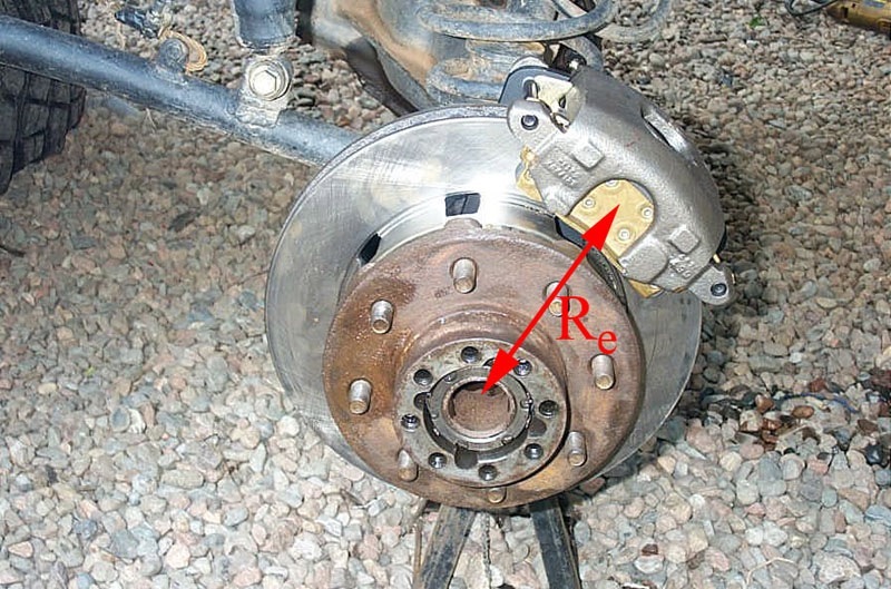
Re — Эффективный радиус тормозного диска (от центра ступицы до центр колодки)
Коэффициент трения
Это индикатор силы трения между тормозным диском и колодкой. Чем выше коэффициент, тем выше сила трения. Для стоковых колодок это коэффициент варьируется от 0,3 до 0,4. Для гоночных от 0,5 до 0,6. "Жесткие" колодки имеют слабый коэффициент трения, при этом изнашиваются меньше. "Мягкие колодки наоборот, имею высокий коэффициент трения и быстрее изнашиваются. Большинство колодок имеет зависимость коэфф трения от температуры, поэтому гоночные колодки необходимо греть, в то время как гражданские при такой температуре уже потеряют свои свойства.
Теплоемкость
Я надеюсь что ни для кого не секрет что тормоза останавливают машину за счет преобразования кинетической энергии в тепло. А значит чем тяжелее машина, чем быстрее вы валите, тем больше тепла она должна рассеивать чтобы не перегреть жидкость, диски и не сжечь колодки. Способность дисков к рассеиванию тепла зависит от их веса и от того как они хорошо охлаждаются.
Формула кинетической энергии движущегося авто:
К = (Вм*См^2) / 2
Где
К — кинетическая энергия (дж)
Вм — Вес машины (кг)
См — скорость машины (м\c)
Тут ничего нового, мы прекрасно понимаем, выбор тормозов зависит от того сколько весит ваш авто и/или как быстро вы ездите. И вы должны помнить еще с автомобильных курсов (для тех кто не покупал права=), что увеличивая скорость в 2 раза вы увеличиваете тормозной путь в 4 раза. Это и есть действие кинетической энергии.
Формула роста температуры при торможении:
Тп = ((Кд-Кп) / (417*Вд)) + Тв
Где
Тп — температура после торможения (С)
Кд — Кинетическая энергия до торможения (дж)
Кп — Кинетическая энергия после торможения (дж)
Вд — Вес тормозных дисков (общий) (кг)
Тв — Температура тормозных дисков до торможения (С)
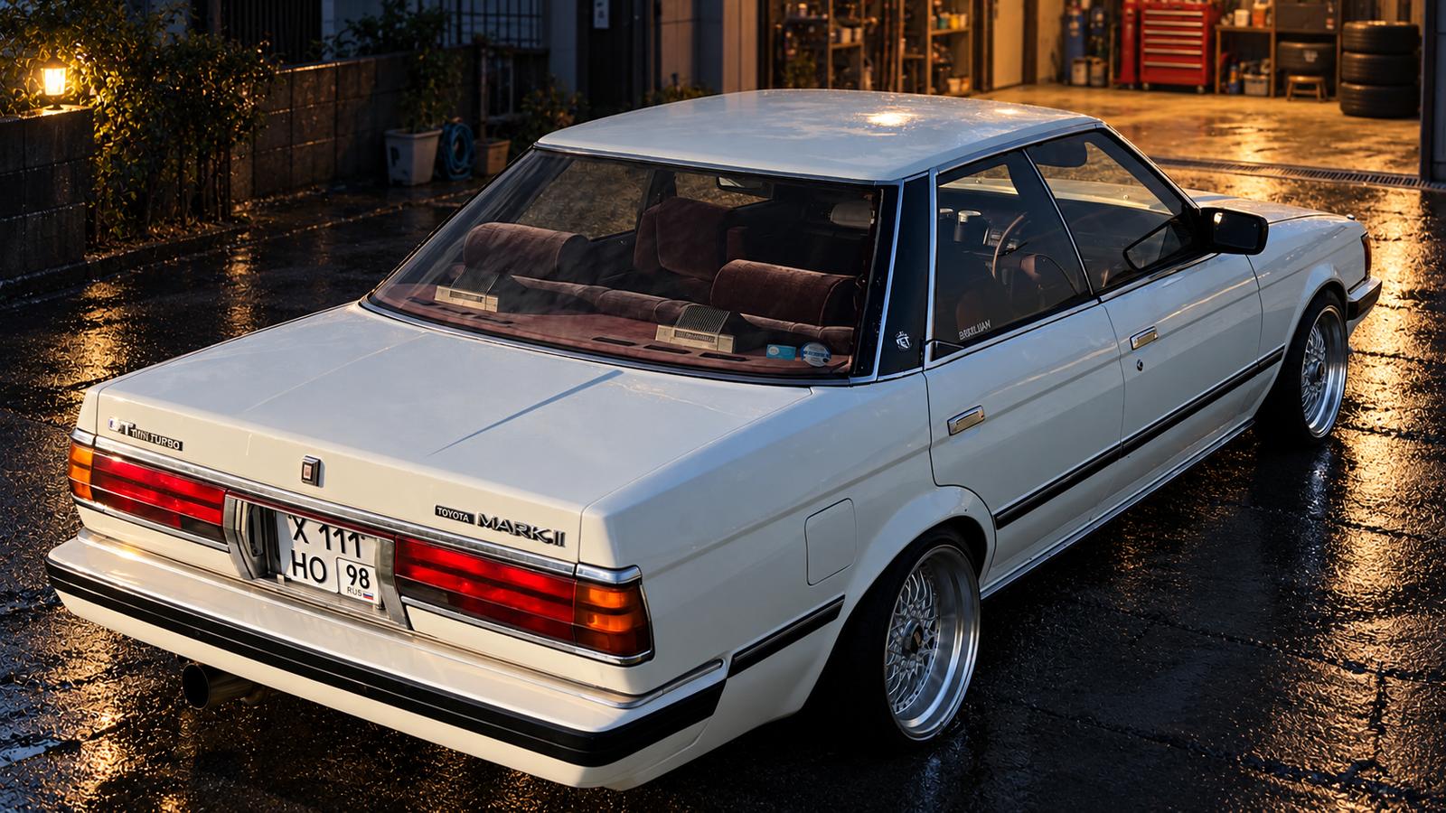
Возьмем к примеру мой авто, торможение перед Т2 в мячково =)
Вес авто — 1220кг
Вес дисков — 33,5кг (перед 12кг, зад 4,75кг)
Скорость на прямой — 177км/ч (49,17м/с)
Скорость перед Т2 — 70км/ч (19,44м/с)
Температура тормозных дисков до торможения — 25С
Кд = (1220*49,17^2) / 2 = 1474826 дж
Кп = (1220*19,44^2) / 2 = 230669 дж
Тп = ((1474826-230669) / (417*33,5)) + 25 = 114 С
И так после такого торможения температура дисков составит около 114 градусов. Давайте сравним с вашими результатами? =) Для простоты можете сказать только вес машины, вес всех тормозных дисков)
И так, с физикой пока притормозим, переидем к более теоретической части.
Есть три вещи которые тормоза должны сделать чтобы остановить авто:
1) Достаточно сильно прижимать колодки к диску
2) Производить достаточную тормозную силу для блокировки колес на любом покрытии
3) Иметь достаточную массу и охлаждение дисков для рассеивания тепла создаваемого кинетической энергией.
Все они в совокупности должны давать отличную информативность.
Педальный узел
Как мы уже обсуждали, чтобы затормозить водитель должен одновременно переместить жидкость и создать давление. ГТЦ перемещает жидкость чтобы создать достаточную прижимную силу колодок к диску.
Педалью вы активируете тормоза, также педаль служит своеобразным рычагом, который увеличивает силу нажатия. Эффект называется "соотношение педали"
Обычно мы давим на педаль тормоза с силой от 22 до 45 кг чтобы активно замедлиться.
Как пример на гоночных авто без усилителя это усилие около 35кг, для машин с усилителем это около 22кг. 45кг это уже перебор, педаль будет очень жесткой.
Соотношение педали можно рассчитать разделив расстояние от точки крепления педали до места приложения силы на расстояние от точки крепления педали до тяги идущей к ГТЦ.
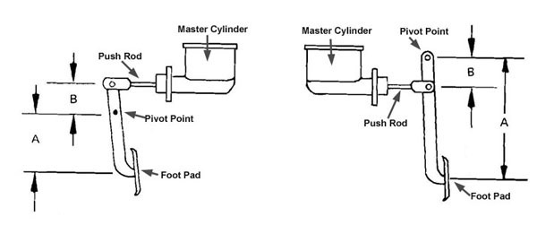
как мы видим, чем больше это отношение тем больше силы передается на ГТЦ. Но нужно помнить один момент, увеличивая соотношение мы увеличиваем и ход педали.
Для машин с усилителем это соотношение обычно около 4-4,5. Для машин без усилителя от 6 до 7.
Поэтому снятие усилителя со стоковой педалью это не верный вариант =)
Гидравлика
Как я уже писал, чтобы прижать колодки к диску необходимо перемещение жидкости и создание давления в контуре. Этим всем заведую законы гидравлики (Паскаля).
В идеале надо стремиться к достаточной силе прижатия колодок при минимальном ходе педали.
Сила приложенная к ГТЦ создает давление в контуре. Давление это сила приложенная к поршню ГТЦ деленная на площадь его цилиндра. А значит чем меньше площадь цилиндра, тем больше давление.
Давление в системе = Сп / Пп
Где
Сп — Сила приложенная к поршню ГТЦ (кг)
Пп — Площадь поршня ГТЦ (см^2)
Приведу пример моего стокового ГТЦ (цилиндр 0,875") при силе 500кг
Давление в системе = 500 / 3,87 = 129 кг/см^2
И с ГТЦ (цилиндр 1")
Давление в системе = 500 / 4,91 = 101 кг/см^2
Из этого следует что чем выше давление тем сильнее колодки прижимаются к диску, а значит больше тормозная сила. Но это еще не значит что если мы хотим мощные тормоза мы должны ставить маленький ГТЦ. Тут вступает другая составляющая — движение. Поскольку жидкость несжимаемая, то любое движение ГТЦ приводит в движение поршни в суппортах. Это движение в гидравлике называют вытеснение. Рассчитывается оно как произведение перемещения поршня на его площадь. Измеряется в см^3
Вытеснение = Пп * Дп
Где
Пп — Площадь поршня (см^2)
Дп — движение поршня ГТЦ (см)
Опять рассчитаем его для стокового ГТЦ моей авто (0.875), и ходом в 3 см
Вытеснение = 3,87 * 3 = 11,61 см^3
И для ГТЦ (цилиндр 1") и ходом 3 см
Вытеснение = 4,91 * 3 = 14,73 см^3
Тут мы видим обратную ситуацию, чем меньше площадь цилиндра, тем меньше вытесняемый объем при том же ходе педали (а значит больше ход педали).
Теперь переходим к разбору полетов о системе в целом, нам известно что тормозная система замкнута а значит давление передается по всей системе в равных значениях. А также в ней кроме ГТЦ есть суппорты с поршнями (для расчетов используется общая площадь всех поршней)
Это значит создаваемое ГТЦ давление приводит в движение все поршни в системе. Поскольку площадь поршней в суппорте больше площади ГТЦ, то по законам гидравлики сила выдаваемая суппортом увеличивается в разы.
Чем большее значение усилия в этом соотношении, тем меньше силы надо прикладывать к педали (и больше ход педали) для достижения того же результата.
Рассчитать усиливающий фактор можно по формуле
Сз = (Сп * Пс) / Пг
Где
Сз — Сила сжатия суппортом (кг)
Сп — Сила приложенная к поршню ГТЦ (кг)
Пс — Эффективная площадь поршней (для суппорта со скобой это 2*на площадь поршней)
Пг — Площадь поршня ГТЦ (см^2)
К примеру опять беру свой авто (цилиндр 0,875") =)
Сз = (500 * 10,17 * 4) / 3,87 = 5255,8 кг
И с ГТЦ (цилиндр 1")
Сз = (500 * 10,17 * 4) / 4,91 = 4142,6 кг
Из этого следует, что при неизменной силе на ГТЦ мы можем увеличить силу сжатия за счет либо увеличения площади поршней суппорта либо уменьшив площадь поршня ГТЦ.
Но не все так просто. Не забывайте о другом факторе — движении. К сожалению играя с площадями цилиндров мы изменяем ход педали. Так, например уменьшая ГТЦ, мы уменьшаем кол-во вытесняемой жидкости — приходится педалью работать больше чтобы компенсировать этот момент (давление не начнет расти пока колодка не прижмется к диску). Это же справедливо и при увеличении площади поршней суппорта (при одном ГТЦ).
Рассчитаем ход поршня:
Хп = (Дп * Пг) / Пс
Где
Хп — Ход поршня суппорта (см)
Дп — Движение поршня ГТЦ (см)
Пг — Площадь поршня ГТЦ (см^2)
Пс — Эффективная площадь поршней (для суппорта со скобой это 2*на площадь поршней) (см^2)
Ну как же без примера? =) Мой стоковый авто (цилиндр 0,875"), ход ГТЦ 3см:
Хп = (3 * 3,87) / 40,68 = 0,29 см
И цилиндр (1")
Хп = (3 * 4,91) / 40,68 = 0,36 см
Из этого мы видим, что если вы не хотите менять ход педали, то изменяя площадь суппорта (ставя огромные тормоза) вы должны не забыть и о ГТЦ. И наоборот.
ГТЦ
Это сердце всей тормозной системы. Активируется нажатием на педаль, вначале поршень передвигает жидкость по системе до тех пор пока колодки не вступят в контакт с диском, затем поскольку система становится замкнутой, начинает расти давление создавая тормозную силу. Отсюда чем сильнее вы давите на педаль тем выше тормозная сила.
Основные параметры ГТЦ это диаметр поршня и его ход. Обычно встречаются ГТЦ с диаметрами от 0,625" до 1,5" и с ходом от 2,5 см до 3,81 см. Соответствие обоих этих параметров к рекомендованным параметрам для вашего авто — залог хорошей производительности. Стоит запомнить при одном усилии на педали, маленький ГТЦ даст большее давление, но при этом сможет меньше вытеснить жидкости. Также чем больше ход ГТЦ, тем больше он жидкости может вытеснить, но при этом бОльший ход педали потребуется. Лучшего результата можно достичь рассчитав компромисс между ходом педали и давлением для вашего авто.
Регуляторы давления
— Клапан остаточного давления (RPV)
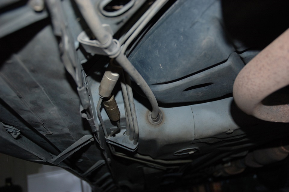
Необходим для поддержания заданного давления в системе (для дисковых тормозов 0.14 кг\см^2, для барабанных 0,70 кг\см^2)
Есть пара причин для использования таких клапанов
1) Только для барабанных тормозов чтобы возвратная пружина не отводила слишком далеко колодки от барабана, создавая лишний ход педали при последующих торможениях.
2) Только для дисковых тормозных систем в которых ГТЦ находится ниже уровня суппортов (некоторые гоночные авто и хот-роды). Без такого клапана жидкость от суппортов будет отекать обратно в ГТЦ делая педаль ватной и опять же увеличивая ее ход.
Если вы меняете барабанные тормоза на дисковые — обязательно удалите из системы такие клапаны
— Дозировочный клапан (Hold-off)
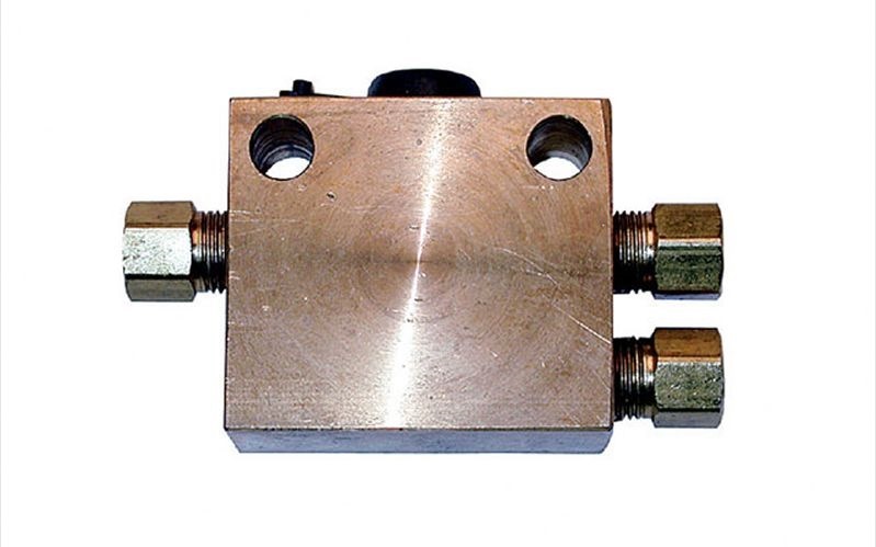
Поскольку на задних барабанных тормозах присутствует возвратная пружина, то как выше описывалось барабанам требуется больший ход чтобы колодка достигла барабана, нежели в саморегулирующихся дисковых тормозах, где колодка всегда впритык к диску. Дозирующий клапан (ставится в передний контур) предотвращает создание давления в переднем тормозном контуре, пока оно не достигнет заданного значения в заднем (обычно до 5-10 кг\см^2) чтобы дать барабанным колодкам приблизиться к барабану.
Если вы меняете барабанные тормоза на дисковые — обязательно удалите из системы такие клапаны
— Распределительный клапан (PBV)
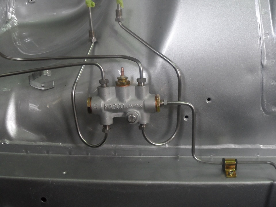
Как мы уже писали выше, при торможении вес машины смещается вперед. Поскольку тормозная сила должна распределиться пропорционально весовой нагрузке (там где больше веса — больше тормозной силы), нужно соблюсти тормозной баланс перед-зад. Например при жестком торможении до 85% веса приходится на перед автомобиля. На правильно отрегулируемой системе передние тормоза и задние блокируются практически одновременно. Устанавливается обычно между ГТЦ и задним контуром чтобы снизить давление на задний контур в первые моменты торможения. Стоит учесть, что давление в заднем контуре не всегда будет ниже чем в переднем, за счет этого клапана вы меняете скорость роста давления. На передних тормозах при нажатии на тормоз оно лишь быстрее создастся чем в заднем.
Стоковые клапана нерегулируемые, но есть и гоночные варианты, с помощью которых можно отрегулировать тормозной баланс на измененной тормозной системе.
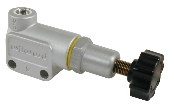
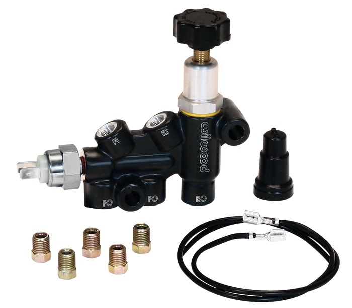
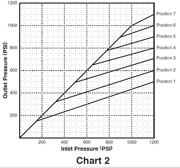
Если вы ставите регулируемый клапан, не забудьте снять стоковый!
— Комбинированные
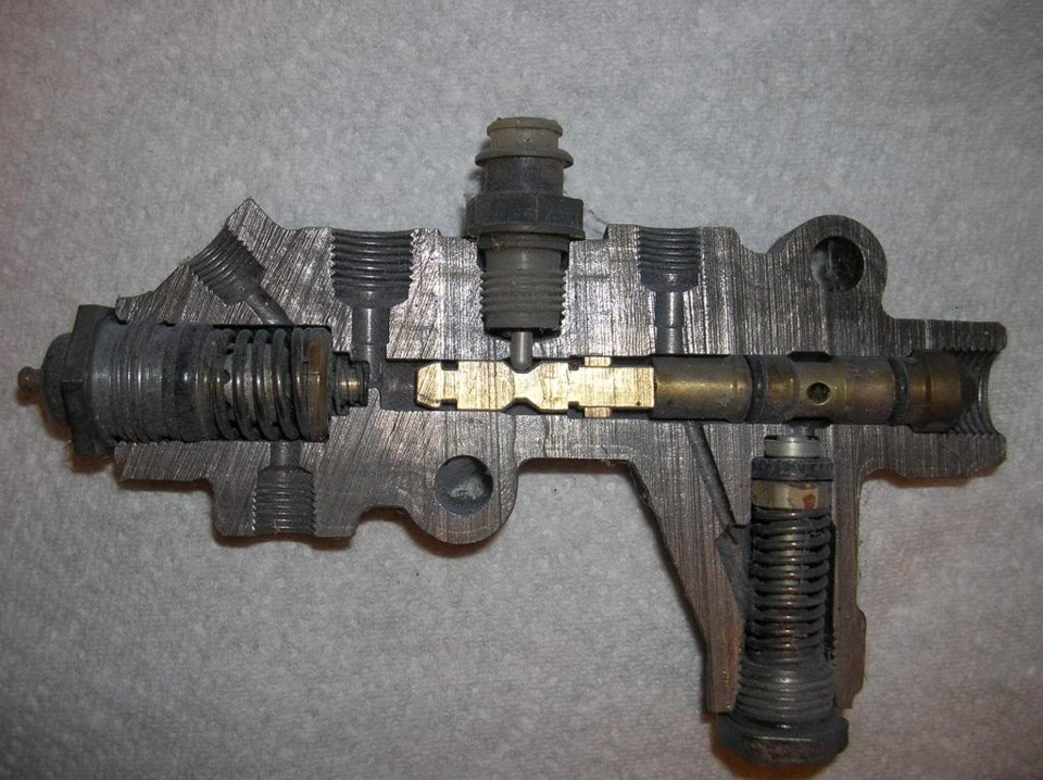
Используются на большинстве стоковых авто с дисково-барабанными системами. Сочетают в себе дозирующий и распределительный клапаны.
Тормозные колодки
Тут все зависит от качества и материала. То на чем не стоит экономить. На хороших брендовых колодках обязательно указывается коэффициент трения! Обозначается он двумя буквами. Первая означает коэффициент трения холодных колодок, вторая горячих
C = до 0.15.
D= 0.15 до 0.25.
E= 0.25 до 0.35.
F= 0.35 до 0.45.
G= 0.45 до 0.55,
H= более 0.55.
Например
Ferodo DS2500 — FF
Hawk HPS — FF
Hawk HP+ — GG
Какой-нибудь сток — FE, то есть горячими тормозить будет хуже чем холодными.
------------------------------------------------------------------------
Итак. Я рассказал о многих нюансах в тормозной системе. Так как же все таки создать правильную тормозную систему с нуля?
Давайте пойдем по порядку
1) Старайтесь использовать тормозные диски необходимого размера для рассеивания кинетической энергии вашей авто (после торможения с максимальной скорости до 0 температура не должна превышать 540 С).
Если вы планируете гонять, то при расчете рассеиваемого тепла используйте температуру тормозных дисков до торможения равной 260 С.
2) Выбрать самый жесткий, крепкий суппорт (чтобы деформация при сжатии диска была минимальной). Использовать суппорт с максимально возможной эффективной площадью поршней.
3) Рассчитать рекомендуемую тормозную силу
4) Рассчитать рекомендуемое максимальное давление в тормозной системе
Рд = ТСр / (µL * Пп * Re)
Где
Рд — рекомендуемое давление создаваемое ГТЦ (кг\см^2)
ТСр — рекомендуемая тормозная сила (кг)
µL — Коэффициент трения колодки и диска
Пп — эффективная площадь поршней (для суппорта со скобой это 2*на площадь поршней)
Re — Эффективный радиус тормозного диска (от центра ступицы до центр колодки)
5) Прикинуть на сколько чувствительную педаль вы хотите. Для спортивного использования например можно взять 35 кг для активного торможения.
6) Выбрать хотите вы тормоза с усилителем или без.
Усилитель нужен например если у вас нет возможности добиться при выбранных компонентах достаточного хода педали и нужного усилия. Или нет возможности установить педаль с высоким соотношением усилия. или у вас ОЧЕНЬ тяжелый авто.
7) Определить соотношение педали, размер ГТЦ, и (если ставился) коэф усилия вакуумника.
Мы знаем какое давление вам надо создать, и насколько вы хотите жесткую педаль. У нас есть три компонента (или два) за счет которых можно создать это давление. Возможно какие-то компоненты вы не захотите менять в своем авто, например тормозную педаль. Значит ее значение можно оставить фиксированным и играть с другими компонентами.
— Соотношение педали
Может быть от 3 до 7. При выборе надо учесте несколько факторов, достаточно ли места для установки, не будет ли педаль упираться в пол до конца хода ГТЦ. Ну и не забывайте чем больше соотношение тем больше ход и ватность педали.
— Рассчитайте силу с которой шток педали будет давить на ГТЦ
Допустим вы хотели бы достигать максимальной силы торможения при давлении на педаль в 35 кг. А соотношение педали у вас 4,5. Значит сила прилагаемая к ГТЦ составит 35*4,5 = 157,5 кг. А если вы используете усилитель, нужно будет умножить еще на коэффициент усиления.
— Выбор правильного размера ГТЦ
Теперь зная рекомендуемое давление, силу создаваемую штоком педали мы можем рассчитать размер ГТЦ
Пп = Сп / Рд
Где
Пп — Площадь поршня ГТЦ (см^2)
Сп — Сила приложенная к поршню ГТЦ (кг)
Рд — рекомендуемое давление создаваемое ГТЦ (кг\см^2)
Допустим нам необходимо давление в 65 кг\см^2, а давить мы можем на ГТЦ с силой 157,5 кг
Пп = 157,5 / 65 = 2,45 см^2
Переведем в типичные для обозначения ГТЦ дюймы
Диаметр ГТЦ в (in) = (2 * (корень из 2,45/3,14)) / 2,54 = 0,695 in
получается нам понадобится цилиндр 11/16 = 0,687 дюймам. Один из самых маленьких. Не забудьте учесть хватит ли его чтобы вытеснить достаточно жидкости.
В случае если не хватит Вам придется увеличивать размер ГТЦ, а значит понадобится большая сила приложенная к поршню ГТЦ чтобы создать достаточное давление. Если не менять соотношение педали — единственным решением будет установка усилителя.
8) Проверить количество вытесненяемой жидкости для выбранных компонентов. Удостоверится что хода педали достаточно для создания силы сжатия.
9) Высчитать создаваемую тормозную силу с компонентами которые вы подобрали и сравнить ее с рекомендованной
Вуаля! =) теперь, если вы все осилили, вы знаете как построить свою тормозную систему или что в ней изменить!
Я надеюсь статья будет очень полезной, и с радостью отвечу на все ваши вопросы и помогу с расчетами если вы сможете предоставить исходные данные:
-Коэффициент усилителя тормозов
-Соотношение педали
-Диаметр ГТЦ
-Диаметр передних поршней + (их кол-во и тип суппорта)
-Диаметр задних поршней + (их кол-во и тип суппорта)
-Сила на педали
-Вес машины
-коэффициент сцепления покрышки с дорогой
-расстояние от передней оси до центра тяжести машины
-колесная база
-расстояние от земли до центра тяжести машины
-Коэффициент трения колодки и диска
-Эффективный радиус тормозного диска (от центра ступицы до центр колодки) перед
-Эффективный радиус тормозного диска (от центра ступицы до центр колодки) зад
-Радиус качения шины (общий диаметр колеса/2)
-Ход ГТЦ
Вообщем с моей машиной, сила приложенная, к педали достаточная для блокировки колес составляет всего лишь 15кг =) В то время типичный сетап для гоночных авто это 35кг и более =)
Комментарии
Пока нет одобренных комментариев.